ATCA-PTSW-AMC4
Table of contents
- 1. DATASHEET
DATASHEET
The ATCA-PTSW-AMC4 board (Pcie and Timing SWitch with 4 AMC slots) is a cutaway quad-AMC module carrier, compliant with the ATCA (PICMG 3.0) specification and compatible with the upcoming ATCA extensions for Physics. Most mid/full-size AMC modules available from industry can be installed in the board.
Its main charateristics are summarized bellow.
PCI Express switch
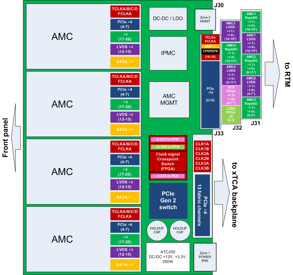
Inbound and outbound data connectivity is predominantly PCIe-based. Data switching is performed by a PLX PEX8696 (PCIe Gen 2), which interconnects:
- 13 fabric channels (×4 links), connecting up to the other 13 PCI Express (PICMG 3.4) compliant modules
- 4 AMC modules (four ×4 PCIe links)
- 1 RTM module (one ×16 PCIe link)
- The onboard FPGA (one ×4 PCIe link)
Clock/timing distribution crosspoint-switch
The ATCA, AMC and RTM timing/clock lines are managed and routed by a crosspoint-switch implemented on a Virtex-6 FPGA.
- The connection to compliant modules within the shelf is assured via the ATCA connector clock and synchronization lines.
- Each clock signal source may be independently located (from any of the AMCs, from the RTM or from the ATCA backplane).
- Support for IEEE-1588-2008 is provided on the FPGA (physical connector on the RTM card).
Rear Transmission Module
The rear transmission module is compatible with the upcoming PICMG 3.8 (ARTM) standard. The card provides digital connectivity on the back-panel of the ATCA shelf and contains the following connectors:
- 1 PCI Express channel (×16 link)
- 1 full-duplex RapidIO channel (×4 link) to each AMC slot (onboard fiber optic transceivers)
- 1 full-duplex RapidIO channel (×4 link) to the FPGA
- 8 LVDS pairs to each AMC slot
- 8 LVDS pairs to the FPGA (reserved for controlling the onboard fiber optic transceivers)
- 1 GbE channel (connects to AMC1)
- 1 GbE channel (connects to the FPGA - for IEEE-1588-2008)
IPMC controller
- CoreIPM OPMA2368
- Hardware management of all AMCs and RTM (IPMB-L)
Block diagram of the board:

